62mm vs 34mm SiC Power Modules: Package Comparison
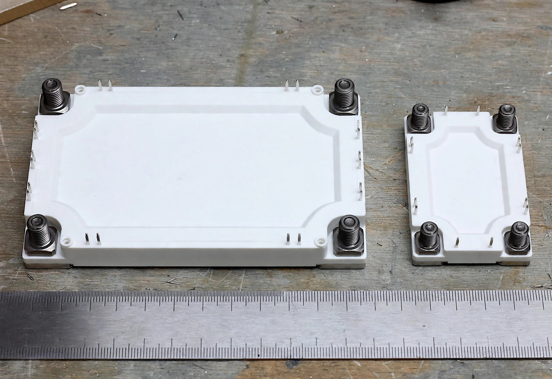
The 62mm and 34mm designations refer to the two dominant industry-standard power module footprints, and both are widely used for silicon carbide (SiC) MOSFET modules. A “62mm module” is a power module with a 62 × 106 mm footprint; a “34mm module” measures 34 × 94 mm. Choosing between them is one of the first packaging decisions in a converter design, and it shapes current capability, thermal design, and even supplier options.
What are 62mm and 34mm modules, and where did they come from?
Both footprints originated in the IGBT era and were carried over to SiC. The 62mm package became the workhorse of industrial drives and inverters: its size allows multiple paralleled chips per switch position, generous terminal spacing for high voltage creepage, and a baseplate large enough for effective heat spreading. The 34mm package serves the compact end — smaller converters where board space and cost per position matter more than maximum current.
Because these footprints are standardized across manufacturers, a 62mm SiC module from one supplier will generally fit the same mechanical envelope as a 62mm module from another. That standardization is what makes second-sourcing and pin-to-pin replacement practical — mechanically, at least. For procurement teams, it also means competitive multi-vendor quoting without retooling the mechanical design, which strengthens negotiating position and supply resilience over the product’s lifetime.
How do the footprints and current ranges compare?
The table below compares the two packages. Current ranges are typical industry orientations, not datasheet limits — always confirm the exact rating for your voltage class and cooling.
| Feature | 34mm module | 62mm module |
|---|---|---|
| Footprint | 34 × 94 mm | 62 × 106 mm |
| Typical current class | tens of amps | ~100 A up to several hundred amps |
| Common voltage classes | 650–1200 V | 650–1700 V |
| Baseplate / heat spreading | smaller area, higher thermal resistance | larger area, lower thermal resistance |
| Terminal current handling | moderate | high, with larger screw terminals |
| Creepage / clearance | adequate for ≤1200 V class | generous, suits 1700 V class |
| Typical topologies | half-bridge, full-bridge, boost | half-bridge, six-pack, chopper, full-bridge |
| Second-source availability | good | excellent — broadest multi-vendor support |
The practical takeaway: if your phase current pushes past roughly the 75–100 A continuous range, or your power stage exceeds ~20–30 kW, you are most likely in 62mm territory. Below that, 34mm keeps the design compact and economical.
Which applications suit each package?
34mm modules fit naturally into:
- Onboard EV chargers (3.3–22 kW), where the charger must fit inside the vehicle
- Auxiliary and standby power supplies in EVs and industrial equipment
- Compact single-phase solar inverters and microinverters
- High-frequency DC-DC stages in data-center and telecom PSUs, where 650 V SiC switches at 100+ kHz
62mm modules dominate where power and thermal headroom matter:
- DC fast-charger power stages (30 kW and up per module position)
- Three-phase solar string inverters and central inverters
- Industrial motor drives and servo drives
- Energy-storage power conversion systems (PCS)
- Wind converter and UPS applications at higher power
Note the overlap: a 20 kW three-phase inverter could be built either way. The 34mm route gives a smaller enclosure; the 62mm route gives thermal margin and easier paralleling for future power upgrades. Your cooling method often decides — if you are already committed to a liquid cold plate, the 62mm module’s larger baseplate uses it efficiently.
What thermal and mechanical differences actually matter?
Three differences deserve attention beyond the headline dimensions:
- Heat spreading. The 62mm baseplate’s larger area reduces thermal resistance from case to heatsink and tolerates higher total dissipation. In a 34mm module running near its limit, the thermal interface material and heatsink flatness become critical — there is less margin for imperfect mounting.
- Paralleling. Higher-power designs often parallel two 62mm modules per switch position. The package’s symmetric layout and well-characterized stray inductance make current sharing manageable. Paralleling 34mm modules is possible but less common, and demands tighter layout symmetry.
- Creepage and clearance. At 1700 V, the 62mm package’s generous terminal spacing is a genuine advantage. Pollution degree, altitude derating, and conformal coating requirements all get easier with more millimeters between potentials.
Can you swap between 62mm and 34mm?
Not directly — the footprints, mounting holes, and terminal positions differ, so moving between them means a new mechanical design and a new heatsink or cold plate. What you can do is standardize: many platform designs use 62mm across a power range (e.g., 30–120 kW) by changing only the module’s current rating within the same footprint, keeping one mechanical and thermal design for the whole family. That platform strategy is one of the strongest arguments for starting with 62mm when your roadmap includes higher-power variants.
Within the same footprint, cross-manufacturer replacement is realistic but requires the full verification methodology — electrical equivalence, gate-drive compatibility, thermal interface, and qualification evidence — which we detail in our replacement methodology guide.
SiC Module Lab stocks and supports both package families across 650 V, 1200 V, and 1700 V classes — send your power level and cooling approach to request samples or an RFQ at /contact/.
Next steps
Shortlist your package by power level and cooling method, then confirm the choice against datasheet current-versus-temperature curves and your loss calculations. If you are weighing 34mm against 62mm for a specific design, contact our team with your bus voltage, output power, and target switching frequency, and we will help you compare options side by side.
Frequently asked questions
What is the physical difference between 62mm and 34mm modules?
A 62mm module measures 62 × 106 mm and a 34mm module 34 × 94 mm. The larger 62mm footprint accommodates bigger dies or more paralleled chips, higher-current terminals, and a larger baseplate for heat spreading — which is why it serves higher-power applications.
When should I choose a 34mm SiC module?
Choose 34mm for space-constrained, lower-power stages: onboard EV chargers, auxiliary power supplies, and compact single-phase inverters. It offers a smaller footprint and lower cost per position where the current demand fits within its thermal and electrical capability.
Are 62mm SiC modules pin-compatible with 62mm IGBT modules?
Often the package footprint and mounting match, since 62mm is a long-standing industry standard. But pin-compatibility of the package does not mean electrical compatibility — gate-drive voltages, switching speed, and overshoot behavior differ, so full verification is still required.
Need samples or a cross-reference check?
Tell us your target application and ratings — our engineers will recommend the right SiC module and arrange samples.
Request Samples