How to Replace Original SiC Modules with Pin-to-Pin Alternatives
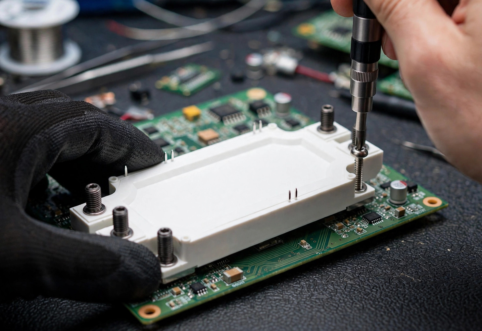
Module replacement means substituting one manufacturer’s SiC power module with another manufacturer’s module that fits the same footprint and meets or exceeds the original’s electrical, thermal, and reliability requirements in your specific application. This article is a methodology guide: it gives you the verification process, not a part-number mapping table. Exact cross-reference data — which alternative matches which original — must always be verified against the current manufacturer datasheets for both parts, because datasheets are revised and ratings change.
Engineers pursue second sources for good reasons: supply resilience, lead-time leverage, cost competition, and protection against single-source discontinuation. The methodology below is how SiC Module Lab evaluates pin-to-pin alternatives for customers, regardless of the incumbent manufacturer.
Step 1: How do you establish electrical equivalence?
Start with a side-by-side datasheet comparison of the incumbent and the candidate, at the same operating conditions. The parameters that matter:
- Blocking voltage (Vds max) — must be equal or higher at the same temperature.
- Continuous and pulsed drain current — compare at the same case temperature, not the headline number.
- On-resistance Rds(on) — compare at the same gate voltage and junction temperature. Note that some manufacturers specify typical values and others maximum; normalize before comparing.
- Switching energies (Eon, Eoff) — compare at matched bus voltage, current, gate resistance, and temperature.
- Gate charge (Qg) and capacitances (Ciss, Coss, Crss) — these determine driver loading and switching speed.
- Body-diode characteristics — forward voltage and reverse-recovery charge matter in hard-switched and synchronous-rectification topologies.
- Thermal resistance Rth(j-c) — per switch position, since it sets your thermal design margin.
Build a comparison table with the test conditions in every row. If a parameter is specified under different conditions in the two datasheets, flag it as “not directly comparable” and plan to measure it yourself. A candidate that is better on Rds(on) but worse on switching energy may still win or lose depending on whether your design is conduction- or switching-dominated — run both through your loss model.
Step 2: Is the gate-drive circuit compatible?
This is where most “drop-in” replacements fail. Even with an identical package, the candidate module has a different internal layout, different stray inductance, and possibly a different recommended gate voltage. Verify:
- Gate voltage levels. If the incumbent is specified at +15/−4 V and the candidate at +18/−3 V (illustrative examples), your existing driver supply rails may need adjustment, and the gate oxide stress must be re-evaluated.
- Gate resistance. The optimal external Rg differs between modules. Start from the candidate’s datasheet recommendation, then tune on a double-pulse test while watching overshoot and ringing.
- Driver capability. Check that your gate driver can supply the candidate’s total gate charge at your switching frequency without overheating, and that its CMTI rating covers the faster edges.
- Protection thresholds. Desaturation detection blanking times and thresholds, UVLO levels, and short-circuit withstand time are module-specific — re-validate every protection setting.
The rule is simple: the gate-drive circuit is designed for a module, not a footprint. Treat the driver as part of the replacement scope.
Step 3: Do thermal and mechanical interfaces match?
Pin-to-pin compatibility covers the electrical terminals, but the thermal path needs equal attention:
- Baseplate dimensions and mounting hole pattern — confirm against both mechanical drawings, including tolerances.
- Terminal positions and heights — busbar and PCB interfaces must align; even a 1 mm difference can force a busbar redesign.
- Internal layout and stray inductance — two modules in the same 62mm outline can have meaningfully different commutation-loop inductance, which changes overshoot at the same di/dt. This is not on most datasheets; measure it.
- Thermal interface — baseplate flatness, surface finish, and recommended TIM. Reuse your existing thermal stack only after confirming the new module’s Rth(j-c) and power-cycling capability support your ΔTj.
- Weight and creepage — heavier modules stress the same mounting; verify creepage and clearance for your pollution degree and altitude, especially at 1700 V.
Step 4: What qualification and reliability evidence is required?
A module that passes bench tests still needs reliability evidence before production. Request and review:
- Power-cycling and thermal-cycling data — curves of cycles-to-failure versus ΔTj, and confirmation that your application’s thermal profile fits within them.
- HTRB (high-temperature reverse bias) and HTGB (high-temperature gate bias) results.
- Humidity robustness (e.g., HV-H3TRB) for solar, outdoor charging, and harsh industrial environments.
- Automotive qualification — AEC-Q101 for the MOSFET chips and the module-level qualification program (such as AQG 324-style testing) if you serve EV customers.
- Change management — the alternative supplier’s PCN (process change notification) policy and long-term availability commitment. A second source without a credible supply commitment is not a second source.
Use the checklist below to track the program:
| Verification item | Source of truth | Typical method |
|---|---|---|
| Voltage / current / Rds(on) equivalence | Both datasheets, same conditions | Comparison table + loss model |
| Switching energy and overshoot | Lab measurement | Double-pulse test in your layout |
| Gate-drive compatibility | Candidate datasheet + driver datasheet | Rg tuning, protection re-validation |
| Thermal performance | Rth(j-c), TIM, heatsink model | Full-load thermal measurement |
| Mechanical fit | Mechanical drawings | Fit check on real hardware |
| Reliability evidence | Supplier qualification reports | Review + application-specific margin analysis |
| System-level behavior | Your converter | Efficiency, EMI, and protection testing |
| Supply commitment | Supplier PCN / availability letter | Procurement review |
Step 5: How do you run the pilot validation?
Do not go from bench test to mass production. A disciplined pilot sequence:
- Engineering samples — double-pulse characterization across temperature, then full-power thermal and efficiency testing on your actual hardware.
- Design verification (DVT) — EMI scans, protection and fault testing (short-circuit, overload, over-temperature), and environmental stress per your product standard.
- Limited pilot build — a few hundred to a few thousand units (application-dependent) through your normal production process, watching for assembly and test-yield differences.
- Field or accelerated-life follow-up — for high-reliability applications, track early field returns against the incumbent’s baseline before full cutover.
Document every step. If the alternative ever needs to be defended in an audit — automotive and energy customers will ask — the verification record is the deliverable that matters.
A note on cross-reference data
You will find pin-to-pin cross-reference tables online, including on this site’s cross-reference pages. Treat every such table as a starting shortlist, not a fact: confirm the exact manufacturer part numbers, voltage and current ratings, and package drawings against the current datasheets before designing anything in. SiC Module Lab publishes cross-reference guidance only where we can tie each suggestion to datasheet parameters, and we re-check mappings when manufacturers revise their documentation.
SiC Module Lab helps customers qualify alternative SiC modules with datasheet-based comparisons, samples, and application testing support — start the conversation with an RFQ at /contact/.
Next steps
Pick your candidate alternative, build the datasheet comparison table from Step 1, and order samples for double-pulse testing. If you want help structuring the comparison or interpreting qualification reports, contact our engineering team with the incumbent module description (e.g., “a 62mm 1200V half-bridge module”) and your application details.
Frequently asked questions
Can I replace a SiC module with another manufacturer's part in the same package?
Mechanically, often yes — standard footprints like 62mm are shared across manufacturers. Electrically, it requires verification: compare blocking voltage, current ratings, Rds(on), switching energies, gate charge, and thermal resistance from both datasheets, then validate with double-pulse and thermal testing.
What is the biggest risk when second-sourcing a SiC module?
Gate-drive and switching-behavior mismatch. Even with identical footprints, different internal layouts change stray inductance, switching speed, and voltage overshoot. A module that looks equivalent on paper can ring or overshoot in your specific layout, so always test in-circuit.
How long does qualifying an alternative SiC module take?
For an industrial application with existing test infrastructure, allow roughly 8–16 weeks: datasheet comparison and sample procurement, double-pulse and thermal characterization, system-level testing, and reliability review. Automotive programs take longer due to AEC-Q101 and PPAP requirements.
Need samples or a cross-reference check?
Tell us your target application and ratings — our engineers will recommend the right SiC module and arrange samples.
Request Samples