SiC Power Modules for EV Charging and Solar Inverters
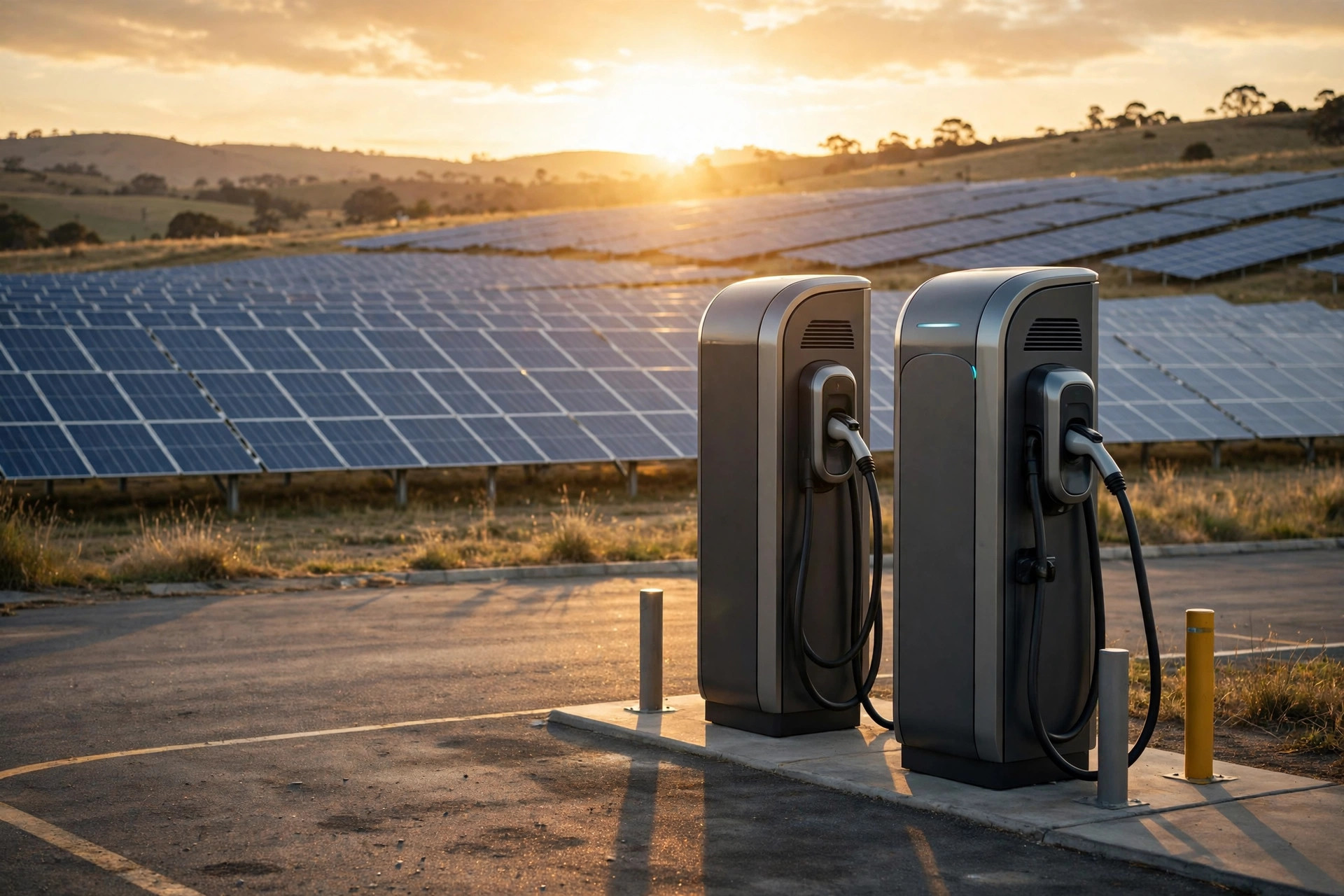
A SiC power module for EV charging or solar inverters is a 650 V, 1200 V, or 1700 V half-bridge, full-bridge, or six-pack module built from silicon carbide MOSFETs, chosen to switch a high-voltage DC bus at tens of kilohertz with minimal loss. These two applications drove SiC’s volume ramp more than any others: both demand high efficiency, high power density, and continuous operation — exactly where SiC’s advantages compound.
Why is SiC suited to DC fast charging?
A DC fast charger converts three-phase AC grid power into regulated high-voltage DC for the vehicle battery, typically in modular 30–60 kW power stages paralleled to reach 120–360 kW per cabinet. The design pressures are brutal: efficiency directly affects operating cost and thermal design, power density determines cabinet size and site footprint, and reliability expectations are automotive-grade.
SiC addresses all three:
- Higher switching frequency (40–80 kHz illustrative) shrinks the PFC inductors and the isolated DC-DC transformer’s magnetics, cutting the size and weight of each power stage.
- Lower switching losses raise stage efficiency into the 97–98%+ range (illustrative), reducing waste heat in sealed outdoor cabinets where cooling is expensive.
- 1200 V devices comfortably cover 700–900 V DC buses used in modern fast chargers, including 800 V-class vehicle architectures, with proper derating margin.
The dominant architecture is a two-stage design: a three-phase PFC front end (often a Vienna rectifier or a two-level/three-level boost PFC using SiC modules) feeding an isolated DC-DC stage (LLC resonant or phase-shifted full-bridge, increasingly dual-active-bridge for bidirectional capability). SiC modules typically serve the PFC stage and the primary side of the DC-DC converter, where hard switching at high frequency extracts the most value.
What topologies benefit most in charging?
| Stage | Common topology | Where SiC modules fit | Why SiC wins |
|---|---|---|---|
| AC-DC PFC | Vienna rectifier, T-type 3-level, 2-level boost | Main switches, 1200 V half-bridge / six-pack | High-frequency hard switching with low loss; 3-level cuts device voltage stress |
| Isolated DC-DC | LLC resonant, phase-shifted full-bridge, DAB | Primary-side bridge | Fast, clean switching; DAB enables bidirectional V2G operation |
| Output filtering | Interleaved buck / parallel stages | Secondary synchronous rectification | Low Rds(on) cuts conduction loss at high output current |
Bidirectional charging (vehicle-to-grid, V2G, and vehicle-to-home) is moving from pilot to product requirement in several markets. Topologies like the dual-active-bridge are inherently bidirectional, and SiC’s low-loss body diode behavior and fast switching make the reverse power flow efficient — a capability worth designing in now even if your first product is unidirectional, since the magnetics and module choices are largely shared.
How does SiC help 1500 V solar inverters?
Utility-scale solar standardized on 1500 V DC arrays to cut cabling and combiner-box costs, and that voltage dictates the inverter’s power stage. Two design approaches dominate:
- Two-level topology with 1700 V SiC modules — simpler control and fewer devices, with the 1700 V class providing proper margin on a 1500 V bus.
- Three-level topology (T-type or NPC) with 1200 V SiC modules — each device sees only half the bus voltage, allowing the broader, more cost-effective 1200 V ecosystem, at the price of more switches and more complex modulation.
Both benefit from SiC’s switching speed: raising the switching frequency from the 8–16 kHz typical of IGBT string inverters into the 16–40 kHz range (illustrative) shrinks the AC filter inductors — some of the heaviest and most expensive components in the inverter — while holding or improving peak efficiency. For transformerless topologies (HERIC, H5, and their three-phase derivatives), SiC’s fast, clean switching also eases the leakage-current and EMI management that transformerless designs demand.
Reliability matters enormously here: solar inverters carry 10–25 year warranties in harsh outdoor environments. Module selection must weigh qualification evidence — power-cycling data, humidity robustness (HV-H3TRB), and HTRB results — alongside electrical performance. The cheapest module that meets the efficiency target is not the cheapest if it drives warranty claims in year eight.
What about energy storage and hybrid applications?
Battery energy-storage systems (ESS) increasingly share hardware platforms with solar inverters — the “solar-plus-storage” PCS (power conversion system) is essentially a bidirectional inverter with a battery port. This convergence favors SiC for the same reasons: bidirectional topologies (DAB, three-level bidirectional PFC) run efficiently on SiC, and a single 1200 V 62mm module platform can span the PV inverter, the battery converter, and the EV charger in a manufacturer’s portfolio.
For designers, the practical consequence is platform leverage: qualify one module family thoroughly — electrical, thermal, reliability, supply chain — and reuse it across products. The engineering cost of qualification amortizes across much larger volume, which is precisely how the SiC TCO case keeps improving.
Design checklist for charger and solar applications
- Voltage class: 1200 V for ≤900 V buses (fast chargers, commercial string inverters); 1700 V or 3-level 1200 V for 1500 V utility solar.
- Package: 62mm half-bridge modules are the mainstream choice for 30 kW+ stages; 34mm suits auxiliary and low-power stages.
- Switching frequency: set by loss budget and magnetics optimization, not by device limits — model both before committing.
- Thermal: sealed outdoor cabinets need conservative thermal design; validate at maximum ambient plus solar loading, not just 25 °C lab conditions.
- Gate drive: isolated drivers with high CMTI, proper negative bias, and validated protection — see our gate driver guide.
- Qualification: power cycling, humidity, and long-term availability evidence matched to 10+ year service expectations.
- Supply: dual-source strategy for the module from day one; see our cross-reference methodology.
SiC Module Lab supports charger and solar designers with 1200 V and 1700 V module options, application review, and samples for double-pulse and efficiency testing — request samples or an RFQ at /contact/.
Next steps
Define your bus voltage, power per stage, and target switching frequency, then shortlist modules using our selection guide and validate with thermal and efficiency testing on real hardware. If you are standardizing a module platform across charging, solar, or storage products, contact our engineering team — platform-level selection is where we add the most value.
Frequently asked questions
Why is SiC preferred for DC fast chargers?
Fast chargers run from 700–900 V buses at tens of kilowatts per power stage. SiC MOSFETs switch efficiently at 40–80 kHz, shrinking inductors and transformers, cutting losses, and enabling compact, high-power-density charger cabinets that IGBT designs struggle to match.
What voltage class of SiC module do solar inverters need?
Modern utility-scale systems use 1500 V DC arrays, which calls for 1700 V SiC modules in two-level topologies or 1200 V devices in three-level topologies. Residential and commercial string inverters on lower bus voltages typically use 1200 V modules.
Can the same SiC module platform serve both EV charging and solar?
Often yes. A 1200 V 62mm half-bridge module family spans DC fast-charger stages, three-phase string inverters, and energy-storage converters. Standardizing on one package across products simplifies procurement, spares, and thermal design.
Need samples or a cross-reference check?
Tell us your target application and ratings — our engineers will recommend the right SiC module and arrange samples.
Request Samples