SiC MOSFET Gate Driver Selection Guide
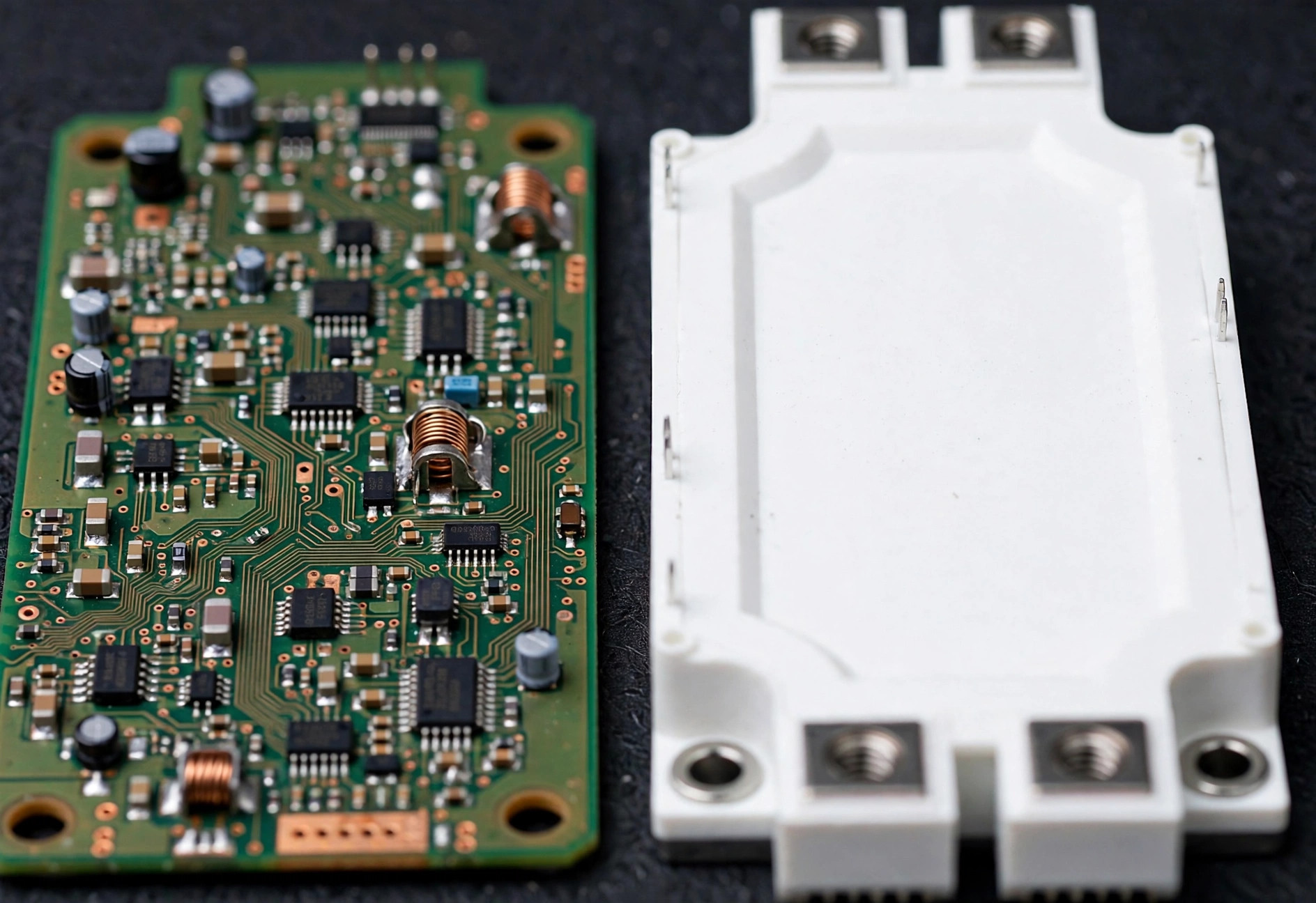
A SiC MOSFET gate driver is an isolated circuit that translates a low-voltage control signal (typically 3.3 or 5 V logic) into the precise gate voltage waveform a silicon carbide MOSFET needs to switch cleanly — delivering high peak current for fast transitions while withstanding the extreme dv/dt the device itself creates. The driver is not an accessory; in SiC designs it is a co-designed part of the power stage, and most SiC field failures trace back to gate-drive mistakes rather than the MOSFET itself.
What gate voltage does a SiC MOSFET need?
Unlike IGBTs, which are happy with +15/−15 V, SiC MOSFETs have a lower maximum gate-source voltage — commonly around +20 V or less — and a threshold voltage of only a few volts. The industry-standard drive levels are approximately +15 V on and −4 to −5 V off, but these are typical values, not universal ones: always design to the specific MOSFET datasheet.
Each rail has a job:
- Positive rail: must be high enough to fully enhance the channel and reach the datasheet Rds(on). Under-driving the gate (e.g., +12 V on a part specified at +15 V) measurably increases conduction loss.
- Negative rail: holds the device firmly off against Miller-coupling-induced parasitic turn-on. With SiC’s low threshold voltage, a 0 V turn-off is risky in half-bridge topologies — the negative bias is cheap insurance.
- Never exceed Vgs(max): overshoot on the gate from layout ringing can punch through the oxide limit even when the supply rails look correct. Probe the gate waveform directly during double-pulse testing.
If you are reusing an IGBT driver, check all three rails before assuming compatibility — this single check eliminates the most common “drop-in replacement” failure.
How much gate current and drive strength do you need?
Peak gate current sets the switching speed: I = Qg / t, where Qg is the module’s total gate charge and t is your target switching time. A 62mm SiC module can present several hundred nanocoulombs of gate charge; switching it in 50–100 ns demands several amps of peak current from the driver.
Size the driver by:
- Peak source/sink current — must exceed Qg divided by your target rise/fall time, with margin.
- Average drive power — P = Qg × Vgs × fsw. At high switching frequency this becomes a real thermal load on the driver and its isolated supply.
- External gate resistor (Rg) — the tuning knob. Too small: ringing, overshoot, EMI. Too large: slow switching that erases SiC’s advantage. Start from the module datasheet’s recommended Rg and optimize on the bench.
Consider split Rg (separate turn-on and turn-off resistors) when you want fast turn-off for short-circuit robustness but controlled turn-on for EMI.
Why do CMTI and isolation ratings matter so much?
SiC’s headline benefit — fast switching — is also its biggest threat to the driver. A 1200 V bus switching in 30 ns produces dv/dt above 30 kV/µs, and that transient drives common-mode current across the isolation barrier. Two specifications decide whether the driver survives its own power stage:
- CMTI (common-mode transient immunity): choose a driver rated comfortably above your measured dv/dt — 100 kV/µs-class or higher is typical for modern SiC drivers, but verify against your actual waveforms.
- Isolation voltage: reinforced isolation rated for your system working voltage with margin, considering transient overvoltages, altitude derating, and the applicable standard (e.g., IEC 61800-5-1 for drives, IEC 62109 for solar).
Optocoupler-based drivers, capacitive isolators, and magnetic (transformer) isolators all serve SiC designs; the choice depends on your CMTI needs, propagation-delay matching requirements, and cost targets. For parallel or multi-channel designs, pay attention to channel-to-channel delay matching — skew between paralleled devices causes current imbalance.
Which protection features are essential?
At minimum, a SiC gate driver for hard-switched applications should provide:
| Feature | What it does | Why it matters for SiC |
|---|---|---|
| Desaturation (DESAT) detection | Senses overcurrent via Vds and initiates soft shutdown | SiC short-circuit withstand time is short (microseconds) — detection must be fast |
| UVLO (undervoltage lockout) | Disables output when supply rails sag | Prevents partial enhancement, which causes extreme dissipation |
| Miller clamp | Low-impedance path holding gate off during the off-state | Suppresses parasitic turn-on from high dv/dt coupling |
| Soft shutdown | Gentle turn-off during faults | Limits voltage overshoot when interrupting fault current |
| Active short-circuit (ASC) | Defined safe state for motor drives | Required by many traction and drive safety concepts |
| Fault feedback | Reports DESAT/UVLO events to the controller | Enables system-level diagnostics and safe restart sequencing |
Set DESAT blanking time carefully: too short causes nuisance trips during normal fast switching; too long lets fault current persist past the device’s withstand capability. There is no substitute for validating protection on a real short-circuit test fixture.
How should the gate loop be laid out?
The gate-drive loop — driver output, Rg, gate, source return — is an antenna and an inductor. Keep it tight:
- Minimize loop area. Place the driver as close to the module’s gate pins as physically possible; every centimeter of trace adds nanohenries that ring with the gate capacitance.
- Use a Kelvin source connection when the module provides one. Driving the gate against the power source terminal couples load-current transients into the gate loop — the number-one cause of mysterious ringing.
- Separate power ground from signal ground, joining them at a single star point.
- Shield or twist gate wiring if the driver cannot sit on the power board.
- Bypass the driver’s supplies locally with low-ESL ceramic capacitors right at the driver pins.
A clean double-pulse waveform — no gate ringing above the threshold, no excessive Vds overshoot — is the acceptance criterion. If the waveform is ugly, no protection feature will save the design.
Common mistakes SiC Module Lab sees
- Reusing an IGBT driver at +15/−15 V without checking the SiC MOSFET’s Vgs(max).
- Zero negative bias (“0 V is fine”) followed by parasitic turn-on failures at temperature.
- Undersized isolated supplies that sag at high switching frequency, tripping UVLO intermittently.
- DESAT blanking copied from an IGBT design, nuisance-tripping on SiC’s faster edges.
- Long gate wiring “because the controller board was already routed.”
Each of these has caused real project delays. All are avoidable with the checklist above.
SiC Module Lab pairs SiC modules with compatible isolated gate drivers — including options from multiple manufacturers' driver portfolios — so you can source the switch and its driver as a validated combination. Request samples or an RFQ at /contact/.
Next steps
Shortlist drivers by gate voltage, peak current, CMTI, and isolation first, then narrow by protection features and package. Before committing, run a double-pulse test with the actual module and driver, probe the gate waveform, and validate every protection threshold under fault conditions. For help matching a driver to your module shortlist, contact our engineering team.
Frequently asked questions
What gate voltage do SiC MOSFETs need?
Most SiC MOSFETs are specified around +15 V on and −4 to −5 V off, but the exact values are datasheet-specific. Standard +15/−15 V IGBT drivers can overstress the SiC gate oxide, while 0 V turn-off risks parasitic turn-on from Miller coupling — always design to the MOSFET datasheet, not the driver default.
Why does CMTI matter for SiC gate drivers?
SiC switches tens of kilovolts per microsecond, and that dv/dt couples across the driver's isolation barrier as common-mode current. If the driver's CMTI rating is too low, the high-side or low-side channel can glitch and cause shoot-through. Choose drivers rated well above your measured switching dv/dt.
Do I need desaturation protection with SiC MOSFETs?
Yes, in most hard-switched applications. SiC MOSFETs have short short-circuit withstand times — often just a few microseconds — so fast desaturation detection with a properly set blanking time is essential. Validate the protection timing on a real short-circuit test, not just on paper.
Need samples or a cross-reference check?
Tell us your target application and ratings — our engineers will recommend the right SiC module and arrange samples.
Request Samples